18 Dec,2019
There are three main cold forming methods of head spinning: Tire spinning, two-step tire free spinning and one-step tire free cold spinning. One step cold spinning without tire puts the slab in one machine to load and spin the desired head, saving time, labor, energy, small area and high production efficiency.
The forming roller device in the rotary cutting machine is similar to the tire mold with tire spinning, but the diameter of the forming roller head is smaller than the diameter of the tire mold. Therefore, during the spinning process, the forming roller will move synchronously from the slab center to the outer edge according to the expected movement track with the spinning roller, and then the head can be finally spun. It can be seen that the motion mode, driving force and self-adaptive synchronous control system design of the forming roll is one of the key technologies that can not be ignored.
The movement mechanism of the forming roller replacing the mould film will directly affect the complexity of the spinning machine and the range of the processing head specification. In order to make the forming roller realize the arc curve motion track required in the process, the existing mechanisms in foreign countries adopt DC motor, which is driven by gearbox. The screw slider rocker mechanism is used for rotation to make the forming roll swing during spinning. Considering the need of spinning small size head and structural rigidity, slider guide is close to the main shaft, so the depth of head is limited when machining large size head, which greatly reduces the capacity of machining head type, that is to say, the specification range of production head is limited.
Therefore, we have innovatively designed a walking mechanism as shown in Figure 2, which can reliably realize the circular arc motion of forming roller. It can effectively ensure the thickness reduction of the processed head and the processing of large-scale deep head, broaden the processing range, and improve the ability of processing head types. The walking mechanism is composed of a swing rod (hydraulic cylinder), a swing rod, etc. The swing rod is a hydraulic cylinder component that can be extended or shortened: the bottom of the hydraulic cylinder is connected with the frame through the hinge, the end of the piston rod is connected with the forming roller gearbox through the hinge; the rocker end that can be adjusted is also connected with the forming roller box, and the other end is connected with the dumpling sleeve on the center line of the spindle box. The piston rod of the hydraulic cylinder is fed, and the forming roller rises close to the main shaft. When the piston rod retracts, the forming roller descends and moves in an arc path. In this way, there is no problem that the slider is close to the main shaft, so as to ensure that the forming roller can stably realize the movement track of the arc curve required by the process; in addition, when spinning the heads of different specifications, only adjusting the oil input of the fixed-point swing rod and the hydraulic cylinder, the sealing heads of various specifications can be spun. This innovative design greatly simplifies the structure of the whole machine.
In the process of secondary pressing, the sheet metal rotates because it relies on the force generated by the main shaft and the forming roller through the junction point to overcome the deformation resistance during spinning. Therefore, it is required that the linear velocity produced by the forming roller and the spindle at the slab engagement point must be the same. For this reason, some foreign companies use DC motor to drive the forming roll and main shaft of the horizontal head flanging machine, and use the speed measuring motor to measure its speed. But this method can only make the two approximate synchronization. The approximate reason is that the meshing point on the surface of the forming roller changes in the deformation area of the slab. When spinning, the tangential linear velocity D. of the engagement point does not change, while the distance a from the engagement point of spinning from the beginning to the edge of the slab changes. When the slab radius RA increases, the spindle speed n decreases accordingly (n = V / 2rr.). When the rotational speed of the forming roller n. is synchronous with the rotational speed of the main shaft n, then n: = V / 2 π R; (n is the drum radius of the forming roller at point a). When meshing at point a, Nen = V / 2 π R; ANRI / R; when spinning to point B, 12U = u, / 2 π R: = NNR: / R2. No doubt R ≠ R, N and N can be seen. The relation of the two is changed with the position of the meshing point. In addition, there are some non-linear and uncertain factors that can not be ignored, so it is difficult to accurately establish the mathematical model and develop the synchronous adaptive speed regulation program of N and ne. Therefore, the speed measuring motor can not detect these changes, so it has to take various improvement or compensation measures, such as installing a overrunning clutch in the speed changing mechanism of the forming roller.
According to the meshing point F, the tangential deformation force is basically constant, and the spinning deformation speed at the meshing point is constant. According to the idea of constant driving power P, the hydraulic oil motor is used as the driving power of the forming roller and the spindle respectively. Based on the working principle of force feedback, the volume speed control synchronous control system composed of the hydraulic oil motor and the constant power variable pump is designed for the first time. The synchronous relationship between the forming roll and the spindle at the meshing point in the forming process of the head is solved.
In the spinning process, if the linear speed of the main shaft and the forming roller at the meshing point is different, the faster bears a larger force, and the power increases correspondingly; the slower bears a smaller force, and the power is small. According to the characteristics of the constant power volume speed regulating system, the power increases and the speed automatically slows down; when the power decreases, the speed automatically increases until the two mechanisms automatically adjust to balance. It can be seen that the force feedback control principle can not only make the control system simple, but also meet the requirements of any meshing point and any instantaneous speed synchronization between the forming roll and the main shaft in the spinning process.
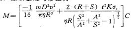
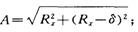
The active rotary motion of forming roller is driven by hydraulic system. Because it drives the slab rotation together with the spindle, the deformation power of the slab spinning forming is equal to the sum of the output power of the spindle and the output power of the forming roller under the condition that the linear speed at the meshing point a is synchronous and normal. According to the energy principle, the total work done by the active torque is equal to the sum of the increment of the rotational inertia kinetic energy of the slab and the work done by the resistance torque, that is, M is the total driving torque, N.m; 9 is the total driving torque The angle of instantaneous rotation, red; OE, J, N.m; s, m; F, friction resistance between spinning roller and sheet metal; R, the radius of rotation at the contact point of slab and forming roller, Mn.


The driving torque parameters of forming roll of FWX20 one-step head cold forming spinning machine in the process of spinning the head with a diameter of 2.4m are calculated theoretically and measured. The results are shown in Figure 4. The theoretical calculation is in good agreement with the measured data. At the same time, the driving moment M., power and rotation speed of the forming roller are also tested. In order to obtain the force and energy parameters of the corresponding position of the spinning head, the radial displacement parameters of the spinning roller are also recorded. The curves of power P., rotational speed Ne and torque M. of the hydraulic motor of the forming roll changing with the radius r of the head are given.
From the measured curve, it can be seen that the design value of the parameters is completely consistent with the measured value, and the operation is stable. When there is an impact of external load, the moment M: jumps, which is equivalent to a step-by-step disturbance of the speed control system, but still stable. With the increase of R and the change of meshing point, the drum radius r decreases, M. decreases, while the rotational speed Ne tends to increase. The application of constant power adaptive synchronous control system in several spinning machines has fully proved its reasonable structure, reliability and stable performance. The whole machine has good working condition, high production efficiency and good economic benefits.

